Database Design Example | MySQL (Part 1)
Let’s take the library as an example
From the client’s point of view — the library is a place where you can get a book and then donate it. Some clients use the possibility of independent selection of literature in the information system of the library. The user does not think about where new books appear in the system, but the librarian brings them there. Also, the information system allows him to find indebted readers and low-demand books. The role of an information system administrator is completely hidden from an ordinary library visitor.
A real library information system is a large and complex system that allows thousands of users to work in parallel and integrates with other library systems.
In the article, we will consider the process of developing a simple information system, however, providing for the roles of a librarian, visitor and administrator.
In this series of tutorials, we are going cover:
1. Infological design:
- Analysis of the subject area and information tasks of users;
- Generation of the data schema;
- Choice of DBMS and other software tools;
- Compilation and normalization of relational relations;
- Normalization of the received relations;
- Determination of requirements for the operating environment;
- Description of user groups and access rights;
3. Formation of queries to the DBMS:
- Creating tables in the database and setting indexes;
- Designing the most demanded requests.
Infological design
1.1 Analysis of the subject area and information tasks of users
The main task of any library is the processing of the book fund. It is easy to distinguish three main groups of users of the system: reader, librarian, administrator. The activity of each is shown in a use case diagram. (picture 1)

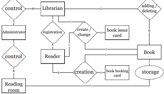
It is already possible to single out some entities and relationships of the future database. (picture 2)

With this approach, it is not clear how exactly to connect the reader with the book (the reader does not have arity in the “issuance / acceptance” relationship. If the book has several copies, then it can be issued to several readers. Even if a book is understood as one copy, then with saving the books of the current reader in the table will make it impossible to obtain information about who (and how many times) took this book earlier.
The solution may be the introduction of an additional entity — a card for issuing a book. When the book is issued to the reader, a card is created, and when the book is handed over, a corresponding mark is put on it. With the help of these cards, the debts of each user are determined and statistics on the use of books are calculated.
When booking literature by the reader, a card is also started; if the booked literature is not taken by the reader within a certain period, the card is destroyed. There is a limit on the number of books a reader can reserve.
When selecting literature, the user views the catalog of literature with the ability to filter the search results by author, title, year of publication.
It is possible to calculate statistics for all books in the library, while the number of issued copies of the book for a given period of time. You can also set the minimum number of book instances for which the calculation is performed. Based on these statistics, unused books are written off from the library.
We single out the following main entities of the subject area:
- user (librarians and administrators);
- reader;
- reading room;
- book;
- book issue card;
- book booking card;
Modified ER database diagram. (picture 3)
According to the use cases shown in picture 1, the database should implement, the following queries (this is not a complete list).
- display books matching given conditions;
- display users who have unclosed issue cards (the librarian is looking for debtors);
- display all books corresponding to unclosed issue cards of the specified user (the user came to the library for new books — you need to see if he is a debtor and inform him about it);
- delete all booking cards created more than N seconds ago;
- display all books corresponding to the specified user’s unclosed book booking cards (the reader ordered books and came to the library for them — the librarian needs to get this list in order to issue);
1.2 Data Scheme generation
To form a data schema, you must first supplement the ER diagram with the details of the entities. At the same time, it is possible to find errors in constructing an ER diagram — in this task, it was found that the book needed to be connected with the library hall. This can be done by adding the detail “room number” in the book, however, with this approach, the same book will have to be described in the database several times (if it meets in different rooms). A more correct approach is to introduce an additional entity “book placement”. ER diagram with added entity and details. (picture 4)

The above ER diagram reflects the main tables, relationships and attributes, on its basis, can build a database model. During the construction of such a diagram, key fields must be highlighted (external and internal). Sometimes — indexes and data types. Database scheme shown below in the picture 5.
And:
- used for links crow’s foot notation;
- tables are shown as rectangles, divided into 3 sections:
- 1. table name;
- 2. internal keys (marked with a marker);
- 3. other fields (marked with a marker);

When developing this model, there was a desire to combine the administrators table with the librarians table — add the users table, however:
- the administrator is not associated with a particular room (would have to fill in the appropriate field null — values);
- this would complicate the distribution of access rights — currently only the database administrator has access to the administrators table (working through a special DBMS panel and not having an account in the system being developed). However, when joining tables, user queries would require access to the new table.
When constructing this diagram, a flaw in the ER diagram was found and corrected — added table librarians_rooms, unifying librarians and rooms. This is necessary, since one librarian can work in several rooms, but several librarians may work in the same room.
